Coil between the barrel and the top and bottom (2)
Coil between the barrel and the top and bottom (2)
Shanghai Xugong Coating Technology Co., Ltd. Xu Guoxing
â—†The front part of this article: the barrel between the steel barrel and the top and bottom (1)
Fig. 5 is a cross-sectional view of the crimping roller 41.
The crimping roller 41 has a forming groove 42 along the circumference. The forming groove 42 is almost D-shaped and opens toward the forming surface 39 of the seaming joint clamping device 31. From the entry side surface 43 of the molding groove 42 (the side on which the flange enters, the right side in the drawing) to the first corner portion 44, the cross section is almost a quarter arc. The groove bottom 45 is connected to the first corner portion 44 and has a linear shape. The radius of curvature of the second corner portion 46 connected to the bottom of the groove is smaller than the radius of curvature of the first corner portion 44, and is also a quarter arc. The outlet side side surface 47 connected to the second corner portion 46 has a linear shape. The introduction surface 48 extends downward from the entry side surface 43, and guides the flanges 12 and 22 that have entered the molding groove 42.
In order to form a good shape, a tight bead seam, the forming groove 42 must meet the following values:
The radius of curvature of the first corner P=(3.0-6.0)t
The radius of curvature of the second corner q = (1.5-4.5) t
The length of the straight portion at the bottom of the groove is D=(0.0-3.0)t
The length of the exit side E=(1.5-4.0)t
The end-curved integral pressing roller 51 reshapes the seamed portion which is seamed by the curling roller 41 in a desired shape, and further presses the center portion to make the seamed portion more compact.
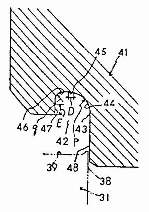
Fig. 6 is a cross-sectional view of the end-curved integral pressing roller which is formed into a substantially rectangular shape in cross-sectional shape of the seamed portion. The end-curved integral pressing roller 51 is provided with a forming groove 52 in the circumferential direction, which is almost rectangular, and has a slit toward the forming surface 39 of the seaming joint clamping device 31. The first corner 54 and the second corner 56 of the molding groove 52 are almost 1/4 arc. Further, the depth n of the molding groove 52 is 1/2 of the thickness of the bead joint portion, and its width W is the same as the height of the bead joint portion.
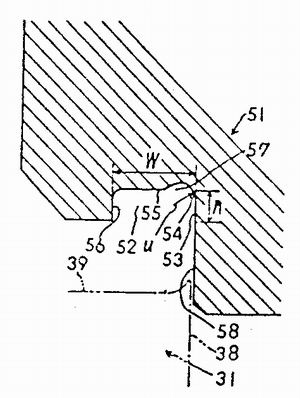
Fig. 7 is an enlarged view of the end-curved integral press roll forming groove shown in Fig. 6. As shown in the figure, the first corner portion 54 of the molding groove 52 is provided with a concave portion 570 having a cross-sectional shape and is smoothly connected to the first corner and the second corner, respectively. The first corner 54 has a substantially 1/4 arc (radius u), the second corner has a radius of approximately 1/6 arc of X, and the depth of the recess 57 is Y.
The appropriate dimensions for each part are as follows:
The radius of curvature of the first corner u=(2.0-2.5)t
The radius of curvature of the second corner X = (O.1 - lO) t
Depth y=0.5t
Further, the guide surface 58 extends downward from the entry side surface 53 of the forming groove 52, and the guide surface 58 guides the flange that has been seamed into the molding groove 52.
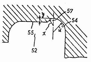
Figure 8 is an explanatory view of the end bending process.
First, as shown in the figure, the tip end portion 23 of the top and bottom flange 22 is bent at the end by bending the integral pressing roller 51 at the end. The end-curved integral pressing roller 51 is moved downward toward the seam seam clamping device 31, and the cylindrical shaped portion 39 of the clamping device is embedded while being held by the crimp seam clamping device 31. The flange tip end portion 23 of the top and bottom 21 is guided into the molding groove 52 by the guide surface 58 of the end curved integral pressing roller. Further, as shown, during the travel along the bottom surface of the recess 57 of the forming groove 52, the flange end portion 23 is less than 90 degrees by the curved concave portion 57 and the radius of curvature of the first and second corners thereof. Arc shape.
A filler supply is provided in the vicinity of the flange tip 13 of the barrel 11 before or after the end bending process.
At the end of the end bending, the end curved integral pressing roller 51 stands by at this position, the curling roller 41 moves downward, and the barrel flange 12 and the top and bottom flanges 22 are caught.
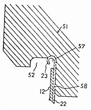
Fig. 9(a), Fig. 9(b), and Fig. 9(c) respectively show the primary stage, the intermediate stage, and the end stage of the seam.
The crimping roller 41 moves downward toward the seam seam clamping device 31, and the flanges 12, 22 enter the molding groove 420 along the guide surface 48. The flanges 12, 22 are bent along the first corner portion 44, passing through the straight line. The groove bottom 45 reaches the second corner portion 46. Thereby, the flanges 12 and 22 which were previously bent by the first corner portion are bent into a curl shape having a larger radius of curvature.
Thus, the flanges 12, 22 are sized in the forming groove 42 by two radii of curvature. After two stages of bending, the bending deformation is smooth, the winding effect of the flange 12; 22 is large, and no excessive deformation stress is generated when bending.
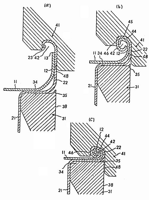
Fig. 10 is a cross-sectional view of the bead joint portion processed by the extrusion forming process.
When the bead seam portion 5 shown in Fig. 9(c) is formed, the hemming roller 41 starts to retreat (rise), and the end bending and pressing roller 51 is lowered. The outer half of the crimped seam portion (the upper half from Fig. 10) enters the groove bottom 55 of the rectangular molding groove 52, and is pressed toward the thickness direction of the seaming portion, Squeezing toward the diagonal direction of the rounded bevel 37 and the crimped seam portion 5, so that the crimped seam portion 5 is correctly and more tightly pressed into a steel drum in a desired shape Crimped seams. A number of voids present between the two flanges are squeezed out to cause direct intimate contact between the metals.
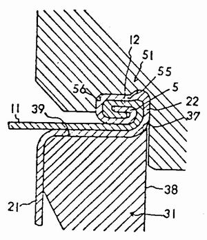
Fig. 11 is a view showing the relationship between the cam rotation angle at which the end portion is bent and the squeezing roller and the hemming roller are lifted and lowered, and the amount of drop of the rollers when the above-mentioned hem seam is formed.
In the figure, the curve I and the curve II respectively represent the crimping roller and the end-curved integral pressing roller. The section K, the section L, and the section M respectively indicate an end bending step, a winding step, and a shaping step.
As shown in the figure, due to the rotation of the cam, the end-end bending roller (before the crimping roller) is first lowered toward the forming surface of the seaming joint clamping device, and the top and bottom flange tips are made. The end is bent; then, the crimping roller is lowered to perform the flange crimping of the barrel and the top and bottom; finally, the end is bent and the pressing roller is lowered (actually, the curling roller is raised, returning In the original position, we carry out the shaping of the hem. Figs. 2, 8 and 9 (a), (b), (c), and 10, and the like, which are shown in the drawings, show the drawings in the molding stage according to the cam rotation angle.
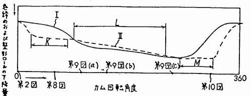
Fig. 12 is an enlarged cross-sectional view showing the crimped joint portion 5 which has been seamed.
The top portion 5a is a portion which is shaped at the inlet side of the molding groove 52 of the end curved forming roll 51 shown in Figs. 6 and 10 . The cross-sectional shape is almost semi-elliptical. The overhanging portion 5b is a portion where the squeezing portion 57 provided in the molding groove 52 of the squeezing roller 51 is bent by the end portion during the shaping. With respect to the central portion 5c, the amount of protrusion I of the projecting portion 5b is preferably about 1/2 of the thickness of the plate. The central portion 5c is pressed by the flat portion of the groove bottom of the molding groove 52 of the end-shaped bending roller 51. Therefore, the barrel flange 12 and the top and bottom flanges 22 are parallel to the barrel body. The central portion 5c is strongly pressed in the radial direction of the barrel, so that the flanges 12, 22 are in direct metal contact with each other in this portion. The filler 9 is distributed at the tips of the barrel flange 12 and the top and bottom flanges 22, and is separated from each other by the curved portions of the flanges. The bottom portion 5d of the crimping joint portion 5 is smaller than the cross section of the top portion 5a, and is almost the same as the top portion 5a. The same shape.
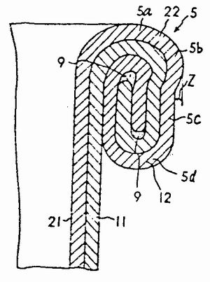
Fig. 13 is another example of the top curved integral press roll forming groove.
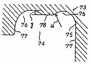
Fig. 14 is an enlarged cross-sectional view showing the seam portion formed by the molding groove shown in Fig. 13. The entry-side and outlet-side sides of the molding groove 74 of the end-curved integral pressing roller 73 of this example are respectively provided with arcuate recesses 76 having the same shape and size. The radius u of the corner portion 75 and the depth y of the recess portion 76 are almost exactly the same as those shown in Fig. 7, and the straight portion 77 and the recess portion 76 are almost one arc-connected. The bottom surface between the concave portion 76 and the concave portion 76 is a bead joint portion formed by the end portion curved pressing roller 73 (the upper end portion and the bottom portion are respectively formed with the projecting portion 6a. Z is almost the same as that shown in Fig. 12. The central portion 6b between the projecting portions 6a and 6a is strongly pressed into a concave shape.
When the seaming portion 6 is subjected to the integral pressing, since the pressing of the end-curved integral pressing roller 73 is concentrated at the center portion 6b, the top and bottom portions of the curling edge portion 6 are not subjected to Excessive processing. Therefore, compared with the crimped seam portion shown in Fig. 12, the curling seam portion 6 has a low hardness at the bottom portion, and when used in a container, the seamed seam portion is deformed even by collision, and cracks are generated. The danger is also small.
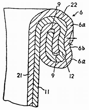
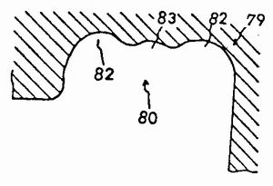
Fig. 15 shows still another example of the end bending of the entire extrusion roll forming groove.
The entry side and the exit side of the molding groove 80 of the end curved pressing roll 79 of this example are respectively provided with the same shape and size. The concave portion 820 is connected to the concave portion 82 between the concave portions 82 and 82 by an arc-shaped concave portion 83. The bead seam portion formed by the end-curved integral pressing roller 79 has a small wave shape as in the center portion 6b of Fig. 14.
The meaning of the numbers listed in the figures:
1- steel drum;
5, 6, 7 - crimping joints;
5a, 6a - extension;
9-filler;
11-barrel;
12 - barrel flange;
21-top and bottom;
22 - top and bottom flanges;
31-Crimping seam clamping device;
34 - forming section;
35 - rounded corners;
37 - rounded bevel;
41-rolling roller;
42 - forming groove;
51-end bending integral extrusion roller;
52, 74, 80 - forming groove;
57, 76, 82 - recess
These premium quality tablewares bundle with cascading metallic dot design are created to effortlessly match the rest of your decorations. The disposable plates are a perfect pairing with the paper cups and napkins supply and are suitable for any season.
Perfect for graduation-themed parties
Graduation Party Supplies--paper platesnapkin cocktail napkin are designedwith graduate elements, such as grad capdiplomabook and so on are clearly printed.
As elegantgraduation decorationsthey will dress your table special and suprise your guests to make the party more fun and attractive.
Tableware,Toilet Mat,Stain Resistant Toilet Rug,Classic Woodgraining Toilet Rug,U Shaped Toilet Rug
HISMOK(SHENZHEN)TECHNOLOGY CO.,LTD , https://www.willtrademat.com