Design of steel drum ground chain conveyor
Design of steel drum ground chain conveyor
Wu Xiping
In the "Steel Barrel" magazine last year, the author has elaborated on the design, principle and structure of the automatic bucket device in the spraying process. In order to solve a series of problems such as the transportation after the completion of the vertical barrel, it is necessary to equip a special equipment - a ground chain conveyor. In this way, it can be combined with the automatic bucket machine to form two sets of professional equipment that are independent and related to each other. To this end, the author combined with his own design practice, wrote this article - the design of the ground chain conveyor. I hope that she can be used as a companion piece to the "design of automatic bucket device" for reference by domestic counterparts.
First, the design purpose
The main purpose is to solve the problem of conveying, diverting and ordering after the barrel of the 200 liter steel drum is sprayed or dried.
Second, the determination of basic parameters
According to the working frequency of the spraying equipment and the automatic vertical bucket device, the working area inside the factory building, and the operating speed that the worker can withstand and adapt, the linear velocity of the conveyor movement can be appropriately selected, generally taking v=0.2-0.4 m/s. It is advisable to select the chain pitch t = 31.75mm, because the constant speed is parallel, so the transmission ratio i = 1 is taken.
Third, the choice of transmission route and structural form
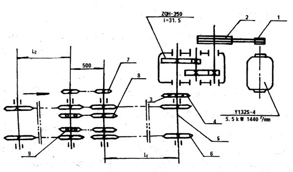
1. Transmission route: As can be seen from Fig. 1, the motion is transmitted from the motor to the high-speed shaft of the ZQH-350 reducer via the V-belt (small pulley 1 and the large pulley 2). After the second-stage deceleration, the transmission is driven by the low-speed shaft. The output of the sprocket 3 is transmitted to the transmission sprocket 4 on the shaft of the driving sprocket, that is, the transmission large sprocket 6 on the coaxial transmission, and the linear transmission of the long distance is transmitted through the intermediate flexible chain and the driven large sprocket. The purpose of the finished barrel.

Figure l Chain conveyor drive diagram
1. Small pulley; 2. Large pulley; 3. Transmission small sprocket; 4. Transmission large sprocket; 5. Active sprocket shaft; 6. Large sprocket; 7. Small sprocket; 8. Fixed sprocket; 9. Follower sprocket.
2. According to the number of steel drums stored in the factory and the maximum conveying length to determine the length of the transmission, if the transmission center distance L <50m can be used for a section; if L>50m, it can be divided into two sections, and the intermediate connection part can adopt relay transmission. The transmission route is such that two fixed sprocket wheels 8 are installed in the middle of the front chain drive driven sprocket shaft, and the follower sprocket 9 installed in the middle of the drive chain sprocket shaft of the rear chain drive is connected by a chain. In this way, the running steel drum can still maintain the original speed through the intermediate and indirect force links when the two sections are connected. From the front section to the rear section, the two sections of the chain are connected end to end and a smooth transition. The power transmission in the rear section is completed by the small sprocket 7 at the shaft end of the two transmission shafts.

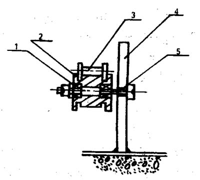
Figure 2 Chain drive bracket diagram
1. Chain axle; 2. Angle steel slide; 3. structural support; 4. Tension wheel.
3. In order to facilitate ground transportation, the conveyor head is placed underground. In order to ensure the stability of the transmission, in addition to making the chain 5 N 10mm above the ground, the long-distance chain should be placed in the track groove composed of two angles of steel, so that the chain does not fall off the rail when moving in the slot, and The highest point of contact between the chain plate and the edge of the barrel is higher than the vertical side of the angle steel, as shown in Figure 2.
Fourth, the tension of the chain
Due to the long distance between the transmission chain center of the conveyor chain, the lower part of the chain is likely to hang too large, which is prone to severe vibration and impact, thus affecting the stability of the entire transmission. For this reason, we have designed a simple roller-type tensioning device. Install one set every 1.5 to 2 m.
The structure of the tensioning device is shown in Figure 3:

Figure 3 Schematic diagram of the tensioning device
1. Rolling bearing; 2. Tension wheel; 3. Chain; 4. structural bracket; 5. tensioning axle.
V. Calculation of required power and shaft diameter
1. Calculate the required power according to the working resistance of the mechanism. First, we conduct an analysis of the organization's forces, as shown in Figure 4.

Figure 4 Mechanism diagram
It is known that v = 0.4 m / s, G barrel weight = 25 kg. The effective length L of the chain drive is 146m, and 115 barrels can be placed.
μ=0.4
The frictional resistance f is analyzed by the force of the unit barrel:
f=N.μ= Gμ......(1)
For the entire organization, there are f total:
f total = ∑ Gμ = 25 x115 x0. 4 = 1150kg
And because P = f total = 1150kg, the power required for work is:
N1=Pv/102 kw......(2)
Generation (2)
N1= 1150X0.4 /102=4.5kw
Also know by the formula motor power N electricity:
N electricity = N1/η total... (3)
η total = η chain × η bearing × η reducer × η belt ... (4)
Find η total = 0.93 x 0.99 x 0.96 x 0.96=0.85
Let η total generation (3) formula, find:
N electricity = 4.5/0.85 = 5. 29kw
Rounding is 5.5kw
According to the work situation, the motor model is selected as follows:
Y132S-40. N=5. Skw. N = 1440 γ / min
2. Estimating the sprocket shaft diameter according to the determined power N and the working revolution n;
The shaft selection material is 45 steel. Considering that the load of the mechanism is stable, the low-speed transmission takes a factor of A=11, which is known from the previous N=5. 5kw, and the working speed is n=20 γ/min.
According to the empirical formula d≥A3√N/n......(5)
After the generation: d ≥ 113 √ 5.5 / 20 ≥ 7.15cm
Rounded d=7.5cm= 75mm
6. Calculation of static tensile strength of conveyor chain drive
For this unit, because the chain speed is v<0.6m/s, it is a low-speed long-distance transmission. It is possible that the probability of damage due to static strength is not large, so the static tensile strength calculation is performed as follows:
Ns=Q/kwP≥4~8......(6)
Where: ns - static strength calculation safety factor,
Q——chain breaking load (kw)
Find Q= 90kN from (Table 14-1*)
Kw - the working condition coefficient, by (Table 14-7*) check kw = 1.3
*Northwestern University of Technology "Mechanical Design" P391 and P400
P - chain working pressure (kN).
By the formula P=1000 N/v (kN)......(7)
Where N is the actual transfer power of the sprocket
N=N electricity × ηN......(8)
In the formula, N=5.Skw, ηN——the total power loss coefficient between the motor and the sprocket, take ηN=0.75, and the generation (8) gives:
N= 5.5 x 0. 75≌4.125(kw)≌4.0(kw)
Then ask for the sprocket line speed v:
By the formula v=n1 XZ1×t (m/s)
Where: n1 - sprocket speed y / min
Z1—the number of active large chain teeth is 38
T——chain pitch, take 31.75
First ask n1:
It is known that n1=n electricity×D1/D2×1/31.5×Z1/Z2......(10)
It is known that D1 = 150 mm and D2 = 180 mm. Z1 = 12, Z2 = 22. Reducer transmission ratio i=31.5
The above data is obtained by substituting (10):
N1 = 1440 × 150/180 x 1/31. 5 x 12/22 = 20. 7y/min. Take n1 = 20y/min.
Substituting the above known data into (9):
v=20 x 38× 31. 75/60×1000=0.4m/s
Then the v value is substituted (7):
P=1000x 4/0.4=10(kN)
The data obtained by Q, P, and kw are obtained by substituting (6):
Ns = 90/1.3 x10=6. 92
Ns≥4~8
Therefore, Ns=6.92 meets the static strength calculation requirements.
Seven, other requirements
The lubrication of the ground chain conveyor shall be carried out in accordance with the general chain drive lubrication requirements. When installing equipment, the problem of waterproofing of the trench should also be taken into consideration. According to the depth of the waterproof layer in each place, the height of the waterproof tank can be determined based on the height of the transmission bracket to ensure the lying underground.
Eight, the conclusion
Because the ground chain conveyor is all lying in the ground, the transportation of the steel barrel is only completed by the friction generated by the chain of 5~10mm above the ground and the bottom of the barrel. Therefore, its advantages are obvious:
1 Because the equipment is not exposed, it can make maximum use of the working area of ​​the plant, eliminating the need for equipment to occupy a lot of space.
2Because its chain runs through the middle of the plant floor, it is convenient for the workers to flexibly carry out the two-side diversion and placement in the process of steel drum transportation according to the quantity of production at any time, which is convenient for the number of inventory, and for the civilized production of enterprises, standardized and orderly Management provides convenience.
3 Due to the smooth and balanced chain drive, and each barrel is placed on the chain, only the bead at the bottom of the steel drum is in contact with the chain, which can greatly avoid the past touch or angle between the steel pipe or the barrel and the barrel. The lacquer layer peeling off due to collision, surface stain damage, and dust adhesion affect the appearance quality.
For the retractable towing rope, its advantages are:
â‘ The operation is flexible and simple, the braking is agile, and the grip is more comfortable;
â‘¡Because the shell is made of sturdy plastic material, it is not easy to be damaged and easy to clean;
â‘¢The length of the traction belt is rich in options, generally 2-8 meters, which can give the pet a sufficient range of activities, increase the amount of activity, and be beneficial to health;
â‘£The traction belt can always be under constant tension, and it can automatically expand and contract, making the pet more free and happy;
⑤The traction belt is easy to clean, and it has a good protective effect on the webbing during use;
â‘¥The color of the shell is more unique, and the fashion sense is rising;
⑦More convenient to carry;
⑧ Especially suitable for small and medium-sized dogs.
The retractable traction rope requires high mechanical structure design, and the braking device requires precision.
Telescopic Traction Rope,Strongest Retractable Dog Leashes,Classic Retractable Dog Leash,Pet Smart Retractable Leashes
DongGuan Lucky Pet Products Co., Ltd. , https://www.dgpetproducts.com