Improvement of the structure of steel drum crimping machine produced in Taiyuan
Improvement of the structure of steel barrel crimping machine produced in Shanxi
Jiangxi Leping Packaging Container Factory Zhengwang Water
Our factory's 200-liter steel drum crimping machine was manufactured in 1984 by Shanxi Water Conservancy Machinery Factory. It was installed and put into operation in 1986.
The crimping machine is the key equipment in the production of steel drums. The performance of the products is directly related to the quality and production efficiency of the steel drums. The design of the aircraft is mainly based on the similar models of West Develd, and is controlled by the US TI1OO microcomputer. The machine is a machine with a high degree of automation. Generally speaking, it has the advantages of novel design, compact structure, good strength and rigidity, and low cost. However, in the structure and layout, the original structural design of the machine is not reasonable enough, so that it can not play its due performance.
The structural problems of the aircraft are mainly:
1. The feeding mechanism is unstable to the control of the workpiece (barrel, bucket top, bottom of the bucket). The loading mechanism is essentially responsible for the two functions of workpiece feeding and positioning, and is indispensable. The reason for the instability of the original feeding mechanism is:
a. The area of ​​the support frame of the loading rack is too narrow, and there is no adjustment device at the fulcrum, which can not guarantee the balance between the correct position and the force point of the barrel;
b. Because the design of the loading frame is taken into consideration, the circular arc surface of the barrel body does not buckle the loading frame, and the front end support point of the loading frame is not allowed to cross the center line of the barrel body, so the center of gravity of the barrel body is forwarded. Tilting
c. Due to the momentum and mechanical vibration of the loading rack, the workpiece is in the middle of the swing, the center of the barrel is not aligned with the axis of the sealing disc, and the headstock is tightened to squeeze the workpiece.
2. The guide plates on both sides have poor support for the top of the bucket and the bottom of the bucket.
a. The original guide plate is lower than the center line of the barrel diameter, and the top of the barrel or the bottom of the barrel is easy to be dumped to the outside of the barrel, and the vibration due to the feeding and the friction between the two sides of the barrel and the bottom of the barrel are uneven. Cause the top of the bucket or the bottom of the bucket to fall easily;
b. Because the guide plate is too short, the operator must be close to the crimping machine to be placed in the top of the bucket and the bottom of the bucket, but can not hide the splashed filler, affecting the operator's attention and work mood.
3. The bearing in the crimping roller has difficulty in adjusting the axial clearance. The crimping wheel of the machine is a wearing part and needs to be replaced frequently. It should be easy to disassemble and adjust. In the roller of the machine, the two 7215 bearings have no axial adjustment device. According to the data, the total thickness T of the 7215 bearing is 30mm, the minimum is 29.5mm, and the tolerance zone is O-1mm. Because of the accumulation error of the roller during the machining process, the thickness of the retaining ring must be matched to eliminate the axial clearance. . When adjusting, it costs a lot of money. Since the axial clearance of the bearing in the roller cannot be eliminated, the roller is unstable after driving, and the groove shape is not allowed to seal the required position of the disk, so it is difficult to ensure the quality of the bead of the steel drum. For the above reasons, the machine has not been put into normal use for a long time in our factory.
In view of the problems existing in this machine, our factory improved some of its structure and designed a set of auxiliary mechanisms suitable for it. After the improvement, the effect is very good. The improvements and usage methods are as follows:
First, the improvement of the feeding mechanism
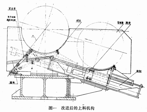
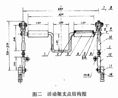
The improved loading mechanism is shown in Figure 1. A movable frame (with a fulcrum) is added to the front end of the bed, and a pair of ball heads (support points) are added at the rear end, and a pair of iron plates and iron plates are attached to each side of the original triangular rib plate of the loading frame. . During operation, the cylinder pushes the loading frame to drive the workpiece forward (feeding), and the iron is blocked. When the iron strikes the roller in the movable frame (see Figure 2), the fulcrum at the top of the movable frame rises and the cylinder is in place. The fulcrum is just against the barrel. Under the cooperation of the fulcrum of the rear ball head, the barrel body is increased in the area of ​​the support point. Thus, the weight of the barrel is basically dropped to the center, so that the alignment of the workpiece and the reel is accurate. And achieved a stable and accurate purpose. After the cylinder is unloaded, the loading frame retreats, and the fulcrum of the movable frame falls below the sliding plate due to its own weight, so that the rolled steel drum can be rolled into the next process.

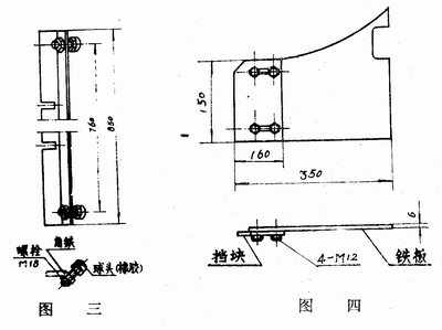
The improved loading mechanism is designed with adjustment devices in each of the added components, and the adjustment of the workpiece position is extremely accurate and convenient. As long as the loading frame is started, the workpiece is lifted and assembled in the sealing disk. First adjust the screw of Figure 2 (11) so that the bearing of Figure 2 (5) is placed against the barrel. It should be noted that the center of the fulcrum (bearing) shall not be higher than the line A of Figure 1 in order to make the movable frame fall, but it is necessary to approach the A line as much as possible to increase the support point area of ​​the barrel. Retain the iron and adjust the screw in Figure 3. Make it put the ball head against the barrel and set it in four points. After adjusting the position of the workpiece, the loading frame is retracted, the workpiece is lowered, and the angle of the movable frame is lowered, so that the bearing (support point) is lower than the sliding plate. If the height is high, the workpiece will be rolled out, and too low will affect the cylinder thrust. At this time, adjust the M18 bolts in Figure 2 and adjust them to work.

1, crankshaft; 2, 104 bearings; 3, 1.5 drums; 4, φ20 circlip; 5, 305 bearings; 6, spacers; 7, φ6 × 35 cotter pins;
8, shaft; 9, M16 nut; 10, ejector; 11, adjusting screw (T20 × 4 left and right teeth); 12, post; 13, hanging feet; 14, screw shaft
Second, the improvement of the guide plate
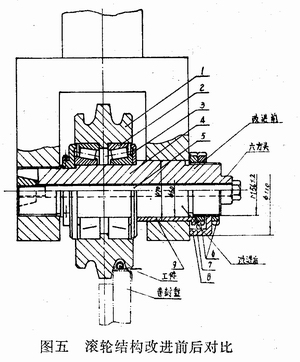
The improved guide plate is both high and long. The purpose of the high is to make the top of the bucket and the bottom of the bucket stable when loading. The purpose of the long is to enable the operator to be as far away from the equipment as possible, avoiding splashing fillers. A barrier protection operator can be established at the vacancy between the device and the operator.

Third, the improvement of the roller structure
The structure of the roller is shown in Figure 5. The upper part is the structure before the improvement, the axial adjustment device without bearings. The lower half is an improved structure with axial adjustment. As can be seen from Figure 5, it is also very easy to change: the shoulder wheel of the original roller shaft of Figure 5 (4) is the same as the inner diameter of the 7512 bearing (φ60), replacing the shoulder with the sleeve of Figure 5 (9), and the original thread M68 ×2 is changed to M56×2, and a round nut and a retaining washer (see Figure 5 (6) (7)) are used to prepare a bowl nut (see Figure 5 (8)).
When adjusting the axial clearance of the bearing, first adjust the round nut (6) M56×2 in the bowl nut (8) so that the sleeve is placed against the retaining ring and the bearing. When the axial clearance is adjusted to the roller, the pendulum is tilted. It can be used when there is a rotation. Fasten the round nut (6) with the retaining washer (7) in Fig. 5, and then tighten the hexagonal head of the shaft (4) to adjust the position of the groove and the sealing disc of the roller (1). After adjusting, tighten the bowl nut (8). Screw a nut (6) on the outside and tighten the screw (5) to work.
After the improvement, not only the adjustment precision is high, but also it is convenient to recite it as a 岑仟 and bag v.

1, roller; 2, 7512 bearing; 3, retaining ring; 4, shaft; 5, lifting screw; 6, M56 × 2 nut; 7, anti-back gasket; 8, bowl nut; 9, bushing
waterproof pet bed,elevated pet bed,pet sofa bed,pet bed cover
Ningbo XISXI E-commerce Co., Ltd , https://www.petspetstoys.com